
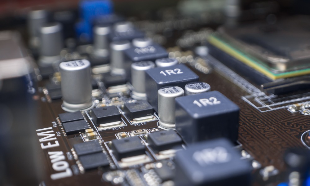
Electronic devices operate amid constant electromagnetic activity. Smartphones transmit wireless signals, factories rely on motors, and medical equipment processes sensitive electronic information. All face a common challenge: unwanted electromagnetic energy can disrupt their performance.
Engineers protect electronics from interference through a combination of techniques that limit electrical disturbances. They identify interference sources, trace how disturbances travel, and protect vulnerable components.
As systems become smaller and more interconnected, these precautions become increasingly important. Reliable protection demands attention to circuit layout, enclosure design, and cable connections.
Understanding Electromagnetic Interference
Electromagnetic interference (EMI) occurs when electromagnetic energy affects electronic equipment. It may originate inside a device or arrive from another source.
Electric motors, switching power supplies, wireless transmitters, and high-speed circuits can generate interference. Lightning and electrostatic discharge can introduce additional disturbances.
Minor interference might create noise in speakers or temporary communication errors. Stronger disturbances may affect sensors, interrupt industrial operations, or cause equipment to malfunction.
Engineers also distinguish between interference that originates within a system and interference generated by nearby equipment. This distinction informs whether they should suppress emissions, strengthen immunity, or pursue both approaches.
How Interference Travels
Engineers distinguish between two main interference pathways.
Conducted interference travels through physical connections, including power lines and signal cables. A switching power supply, for example, may introduce electrical noise into circuitry.
Radiated interference travels through electromagnetic fields without direct electrical contact. Circuit traces and cables can act as unintended antennas, allowing nearby equipment to receive disturbances.
Identifying the pathway helps engineers select appropriate measures to protect electronics from interference.
Using Shielding to Block Unwanted Signals
Electromagnetic shielding creates a barrier between interference sources and vulnerable components. Engineers select conductive or magnetic materials according to the field characteristics and operating conditions.
At low frequencies, magnetic fields may require different shielding approaches than high-frequency electric fields. Consequently, engineers evaluate actual field behavior instead of assuming that every metal sheet offers equivalent protection.
Choosing Suitable Shielding Materials
Copper and aluminum are common choices for radio-frequency shielding because their electrical conductivity supports attenuation of electromagnetic fields.
Copper suits conductive enclosures, contacts, and precisely fabricated shielding components. Aluminum provides a lightweight alternative when designers maintain suitable electrical connections.
Material selection also depends on mechanical strength, corrosion resistance, manufacturing requirements, and frequency.
Fabrication affects the finished shield’s performance. Thickness, forming characteristics, and electrical continuity are all significant aspects of copper sheets for RF shielding.
Why Enclosure Design Matters
A conductive enclosure cannot provide consistent protection when electromagnetic energy passes through openings or poorly connected joints.
Ventilation slots, access panels, and cable openings can weaken shielding. Long gaps along seams may create additional leakage paths, especially at higher frequencies.
Engineers manage opening dimensions and maintain conductive contact between adjoining surfaces. Conductive gaskets improve connections around removable panels, while carefully designed joints preserve access for maintenance.
Effective shielding depends on the complete assembly, not simply its material.
Designing Circuits to Minimize Interference
Shielding helps block external disturbances, but engineers can also reduce interference at its source.
Printed circuit board (PCB) layout matters because electrical signals travel through closely spaced conductive pathways. Poor routing or component placement can allow energy to affect neighboring circuits.
Separating Sensitive Components
High-speed digital circuits and switching power components may disturb sensitive analog signals. Designers reduce this interaction by arranging components carefully and managing their electrical return paths.
Physical separation helps, but distance alone cannot guarantee protection. Engineers also examine current flow and electromagnetic coupling within the board.
Managing Circuit Paths
Current travels through a complete circuit, including its return path. Poor return-path design can create larger loops that increase electromagnetic coupling.
Continuous reference planes can provide controlled return paths when implemented correctly. Designers also limit unnecessary trace lengths and account for signal behavior at higher frequencies.
Controlling Interference Through Grounding and Bonding
Grounding and bonding affect how unwanted currents move through equipment, but they serve different functions.
Grounding establishes an electrical reference or connection to earth, depending on the system. Bonding creates conductive connections between metal structures or equipment components.
Both can support electromagnetic compatibility when engineers account for operating frequencies and current paths.
Maintaining Electrical Continuity
An enclosure may contain several panels joined with fasteners. Connections with excessive electrical impedance can compromise shielding performance.
Engineers evaluate contact resistance, joint geometry, and return paths. They also consider how coatings and corrosion affect metal-to-metal contact.
A connection that works for electrical safety may not provide a sufficiently low-impedance path for high-frequency interference. Effective grounding and bonding therefore require deliberate design.
Filtering Unwanted Electrical Noise
Interference can enter equipment through power and signal cables even when the enclosure provides adequate shielding. Filters suppress disturbances while allowing power or signals to pass.
Selecting Appropriate Filters
Capacitors and inductors form many filter circuits. Capacitors can divert high-frequency disturbances from sensitive paths, while inductors resist changes in current.
Engineers combine these components to address specific frequency ranges. Ferrite components can also suppress high-frequency currents on cables when correctly selected and installed.
Filter performance depends on circuit impedance, component characteristics, and placement. Poor installation may allow noise to bypass the intended filter.
Protecting Cable Connections
Cables can transfer interference between otherwise protected devices. Engineers use appropriate shielding, controlled routing, and filtering near enclosure entry points.
Correct shield termination matters. A poorly connected cable shield can undermine an enclosure’s protection.
The best arrangement depends on the frequencies and the system’s electrical design.
Testing Electronic Equipment for Interference
Calculations cannot reveal every electromagnetic compatibility problem. Manufacturing variations and unexpected component interactions can change performance.
Testing identifies weaknesses before equipment enters service.
Engineers may use oscilloscopes and near-field probes during troubleshooting to locate problematic switching activity or unintended coupling. These measurements guide targeted changes before formal compliance testing begins.
These checks help engineers spot problems before final certification.
Measuring Emissions and Immunity
Electromagnetic compatibility (EMC) testing addresses emissions and immunity.
Emissions tests measure the electromagnetic energy a device produces. Engineers examine emissions using methods that suit applicable frequencies and requirements.
Immunity tests assess whether equipment continues operating acceptably when exposed to specified disturbances. Tests may involve radio-frequency fields, electrical transients, or electrostatic discharge.
Evaluating Performance Under Realistic Conditions
Controlled laboratory tests matter, but actual environments introduce further challenges.
Factories contain motors and extensive electrical infrastructure. Hospitals operate sensitive devices near other equipment. Transportation systems combine communication technologies with demanding electrical loads.
Engineers assess these conditions and examine how installation practices, cable arrangements, and maintenance affect performance.
Why Interference Protection Requires a Complete Approach
No single method eliminates every interference problem. Shielding may reduce radiated disturbances, yet poor cable connections can create alternative entry paths. Filters suppress conducted noise, but inadequate circuit layout may still generate unwanted emissions.
Engineers therefore coordinate protective measures throughout product development. This integrated approach strengthens EMI protection by addressing energy at its source and along the paths through which it reaches vulnerable components.
As connected infrastructure and automated systems expand, reliable electromagnetic compatibility becomes increasingly important. Careful design, effective materials, and systematic testing help electronic equipment function consistently despite surrounding electromagnetic activity.

 The World Beast

